

What is a resistor?
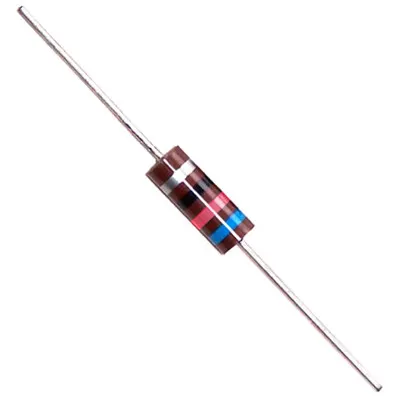
A resistor is a passive electronic component that blocks the flow of electrical current.
Have you ever seen an LED being lit? With the resistor, it can shine brightly instead of being burned.
The value unit of resistance is Ohm (Ω), which conforms to Ohm’s law in the circuit.
The international symbol is a rectangular box, but the standard symbol for the US is a wavy line.
The resistors in the circuit are named differently according to the working position. And the power, resistance, type, and withstand voltage are different, but they are all called resistors.
common type
The resistors in the circuit are named differently according to the working position.
But the resistance is still the same, but the power, resistance value, type, withstand voltage, etc. are different.
Current limiting resistor
The current-limiting resistor is to avoid local excessive current from burning out components. The current-limiting resistor is connected in series with the circuit by resistors to limit the current in the circuit to prevent excessive current from burning out the components connected in series.
The most common circuit is the LED indicator light. A resistor is connected in series to limit the current within the rated operating range of the LED to ensure that the LED works normally and will not be damaged due to voltage fluctuations. It can also be called a voltage divider resistor.
The base resistor of the triode is a current limiting resistor to prevent the base current of the triode from being too large and saturated.
Pull-up and pull-down resistors
The pull-up resistor and the pull-down resistor are to clamp the circuit state at high level and low level through a resistor. If there is no pull-up and pull-down resistor, the state of the circuit will be an unknown state, which may be low level or high level. It can also be the level of jumping.
The resistance value of the pull-up resistor is different, and the pull-up ability is also different. The resistance value is selected according to the circuit function. The smaller the resistance value is, the higher the power consumption of the circuit is, the higher the resistance value is, the weaker the pull-up ability is, and the appropriate resistance is selected according to different needs. value.
The open-collector circuit must use a pull-up resistor to improve the high-level load capacity of the output. In order to enhance the driving capability of the output pin, a pull-up resistor is also used on the pin of the chip. In order to prevent electrostatic interference damage, unused pins are generally connected to pull-up resistors to improve circuit stability.
Add pull-up resistors to the pins of the chip to increase the output level, improve the input signal of the chip, and enhance the anti-interference ability. To improve the anti-electromagnetic interference capability of the bus, it is easier to accept external electromagnetic interference by floating the pins.
In the long-term transmission, the mismatch of the resistance can easily cause the reflected wave interference. In addition, the pull-down resistor is the resistance matching, which can effectively suppress the reflected wave interference. The downside of pull-up resistors is that they consume extra energy when current flows through them.
Now many chips have integrated pull-up and pull-down resistors, which can be turned on or off through the program during design. Thereby reducing the system operating current.
Current sense resistor
The most common components used to sense current are low value precision resistors placed in the current path.
This resistor is usually used to measure the current in the circuit, so it is called a current-sensing resistor. When the current flows through the resistor, a voltage proportional to the current passing through it will be generated at both ends.
Due to the small resistance of the shunt resistor, the effect on the current is negligible, and the resistance value is from milliohms to hundreds of milliohms (mΩ). Therefore, the voltage generated at both ends of the shunt resistor is also very small. If MCU acquisition is required, an operational amplifier or a dedicated current detection amplifier must be used to amplify the voltage generated at both ends of the shunt resistor to a certain voltage, so that the voltage can reach the measurement range of the MCU. .
The voltage signal can be digitally processed, and the result information can be displayed on the display screen or used as a feedback loop to control the loop current.
Divider resistor
The voltage divider resistor is to pass the high voltage through different resistance resistors to obtain different voltages. The voltage divider resistors are connected in series on the circuit, which will play the role of voltage divider, and a part of the voltage will drop on the voltage divider resistors.
The voltage divider resistor usually goes into a comparator to judge whether the two voltages are within a certain range. In order to control the size of the voltage in the circuit and whether to protect the action.
Common voltage detection, voltage protection, reference circuit, etc.
(Picture of Wonderful Chip)
Discharge resistance
The discharge resistor is the resistor used to discharge, and the discharge resistor is usually connected in parallel with the capacitor. Ensure that after the equipment is powered off, if the discharge resistor is not connected in parallel, quickly discharge the voltage in the capacitor, so as to avoid the risk of electric shock during maintenance due to the voltage stored in the capacitor.
It is the most common at the input end of the switching power supply, and the resistance value is usually large, reaching the megohm level.
bias resistor
Bias resistor, the bias resistor is the most widely used, no matter in the triode amplifier or op amp amplifier circuit, the bias resistor is needed, from the working range of the triode, there are three areas, the saturation area, the amplification area, and the cut-off area.
When the triode is working normally, it needs to work in the amplification area to amplify the signal. At this time, the tiny signal at the base can control the voltage signal of the collector and emitter.
In order to make the triode work in the amplification area, it is necessary to provide an operating voltage to the three poles of the triode. In order to obtain this voltage, it is necessary to add a bias resistor to the triode so that the three pole voltages of the triode meet the requirements of the triode working in the amplification area.
Its main function in the amplifying circuit is to provide an appropriate base current so that the amplifying circuit can obtain a suitable operating point and make the emitter junction in a forward bias. The purpose of adding a bias resistor to the triode is to keep the triode in an amplified state at all times.
If no bias resistor is added, the triode has no bias voltage. If the triode works in the saturation region and the cut-off region, the collector and emitter collector currents will not change with the change of the base, and the triode can only be used as a switch at this time, not as an amplifier.
Load Resistance
A resistor is connected in parallel in the power supply circuit. This resistor is called a load resistor. It is widely used in switching power supplies. The purpose is to stabilize the power output and avoid shocks. The resistor will continue to generate heat when it works for a long time, so a high-power resistor should be selected.
(Picture of Wonderful PCB)
Resistance good or bad detection
Check the appearance without scorching, cracks, and corrosion. For power resistors, long-term work and heat are likely to cause false welding, which is the most likely failure in the circuit. It is common that the resistance value becomes larger, open circuit and so on.
Note that when testing, the test resistance value in the circuit will be inaccurate. If you suspect that there is a problem with the resistor, you should remove it for measurement or pick up a leg to measure again.
About Wonderful

(Picture of Wonderful Chip)
Shenzhen Wonderful Technology Co., Ltd. is China’s top model and small batch circuit board manufacturer.
The company targets precision circuit board samples and small batches as the main target market. Since its establishment, it has adhered to the development concept of good quality and important reputation.
Invest huge sums of money to introduce advanced equipment, strictly regulate the operating standards and QC standards for incoming and outgoing materials, to ensure that the shipped products reach Seiko quality.
The self-developed ERP management system can realize the whole process of paperless operations such as online ordering, online payment, online production progress query, online logistics tracking, and online statistical report production, which greatly improves work efficiency.
It ensures that each order can be shipped quickly. After more than ten years of development, the company’s products and services have been well received by the market.
As well as the opening of an electronic component mall, integrated circuits, semiconductors, resistors, capacitors and other products are sold.
The company’s scale is developing rapidly, and the sample and small batch shipment capacity reaches 500 models/day.
The products are widely used in communications, medical equipment, industrial control products, aviation, military products, testing instruments,Automotive, computers and other peripheral products.
We will continue to pay attention to customers, with efficient delivery speed and perfect after-sales service, to become the most trusted brand supplier in the PCB industry.
Wonderful PCB You can send us your requirements first. Click here to contact us.
You can click our component store. Please click here to contact us.


 English