

10 Methods of PCB Thermal Resistance Layout
The thermal resistance of a PCB specifies the resistance to heat dissipation, a number that indicates how easily the heat is transferred.
Thermal Resistance The temperature difference between any two points divided by the heat flux flowing between the two points.
Low thermal resistance in the PCB makes it easier for heat to dissipate. At the same time, the thermal resistance of the PCB can also be calculated by evaluating the thermal parameters of all layers and materials of the board.

To find the total thermal resistance of a board, one must include all the layers of the board and the relevant thermal parameters for the type of material through which the heat will flow.
A high thermal resistance value means that heat is difficult to transfer, while a low thermal resistance value means that heat is easy to transfer.
The symbols for thermal resistance are Rth and θ. Rth comes from the English expression “thermal resistance” for thermal resistance. The unit is °C/W (K/W).
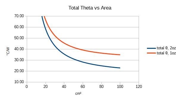
Image courtesy of Paul Bryson of brysonics.com
PCB Thermal Resistance Management and Layout
1. The thermally sensitive devices are placed in the cold air area.
2. The temperature detection device is placed in the hottest position.
3. Devices on the same printed board should be arranged as far as possible according to their calorific value and degree of heat dissipation.
Devices with low heat generation or poor heat resistance (such as small-signal transistors, small-scale integrated circuits, electrolytic capacitors, etc.) are placed at the entrance of the cooling airflow, and devices with high heat generation or good heat resistance (such as power transistors, large-scale circuit, etc.) on the outlet of the cooling air flow.
4. The high-power devices should be arranged as close to the edge of the printed board as possible to shorten the heat transfer path; in the vertical direction, the high-power devices should be arranged as close to the top of the printed board as possible to reduce the influence of these devices on the temperature of other devices during operation.
5. The heat dissipation of the printed board in the equipment mainly depends on the air flow, so the air flow path should be studied in the design, and the device or printed circuit board should be reasonably configured. When air flows, it always tends to flow where there is less resistance.
Therefore, when configuring devices on a printed circuit board, it is necessary to avoid leaving a large airspace in a certain area. The configuration of multiple printed circuit boards in the whole machine should also pay attention to the same problem.
6. Devices that are more sensitive to temperature are best placed in the area with the lowest temperature (such as the bottom of the device), not directly above the heat-generating device, and multiple devices are best staggered on the horizontal plane.
7. Arrange the devices with the highest power consumption and heat generation near the best heat dissipation location. Do not place high-heat components on the corners and edges of the printed board unless a heat sink is arranged near it.
8. Add radiator and heat-conducting plate to high-heat-generating devices. When there are a few devices in the PCB that generate a large amount of heat, radiators or heat-conducting pipes can be added to the heat-generating devices.
A radiator with a fan can be used to enhance the cooling effect.

IC Layout
1. For equipment cooled by free convection air, it is better to arrange the integrated circuits vertically or horizontally.
2.It is necessary to conduct thermal performance analysis of printed circuits. The added thermal performance index analysis software module can help designers optimize circuit design.
Shipping! Shipping!🤩#Manufacturing #PCBA pic.twitter.com/JRPrjH2NOj
— Wonderful PCB (@WonderfulPCBA) August 31, 2022


 English